Difference between revisions of "Setup"
| Line 45: | Line 45: | ||
''Add USB'' | ''Add USB'' | ||
| + | |||
This option is to be used to define a DMX, Pixelnet, LOR dongle, DLight, Renard or OpenDMX setup. Each USB choice is described in the text found below the dropdown selection. | This option is to be used to define a DMX, Pixelnet, LOR dongle, DLight, Renard or OpenDMX setup. Each USB choice is described in the text found below the dropdown selection. | ||
As you select a different choice, the text assists you in identifying the best choice for your USB dongle. | As you select a different choice, the text assists you in identifying the best choice for your USB dongle. | ||
| Line 51: | Line 52: | ||
''Add E1.31'' | ''Add E1.31'' | ||
| + | |||
Clicking on the Add E1.31 button will display the following screen: | Clicking on the Add E1.31 button will display the following screen: | ||
| Line 87: | Line 89: | ||
If universe 1 is set to 32 channels, then Universe 2 will start from 33 onwards that is also a valid configuration. | If universe 1 is set to 32 channels, then Universe 2 will start from 33 onwards that is also a valid configuration. | ||
| − | [[File: | + | [[File:Setup_7a.png]] |
''Add NULL'' | ''Add NULL'' | ||
Latest revision as of 03:55, 28 October 2015
Contents
Setup
The Setup tab is used to define the locations of the Show and Media directories as well as to configure the details of your network for each Universe.
Directories
Show Directory
The xLights/Nutcracker Show Directory is where all the required xLights/Nutcracker sequences, pictures, and user configuration files required to run the sequences are kept. When a sequence (.xml) is saved and a binary file (.fseq) rendered, both files are created in the show directory. This is the same location where xLights/Nutcracker configuration files can be found and the default location where the program will first prompt for, or look for files pertaining to several functions of xLights/Nutcracker.
Tip: It is useful to have separate show directories for each major event i.e. one for Halloween, one for Christmas or one for the next year. Start a new year directory by copying sequences from the Show Directory of the previous year.
Media Directory
The xLights/Nutcracker Media Directory is where the required audio (.mp3) and video (.mp4) media files are kept. The media directory can be different to the show directory or can be the same directory. This is the default location where xLights/Nutcracker will first prompt for, or look for media files.
Tip: It is useful to have a common media directory for all shows. Alternatively, place all of the media for a particular show event in the respective show directory and set both of them to be the same.
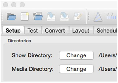
Specifying the names of these directories or changing them can be done by clicking on the Change button found on the Setup tab screen. If the two directories have been linked together (via the link icon), then the user can only change the location of the Show Directory and the same change will apply to the Media Directory.
If separate locations are required, click on the icon to unlink the directories, at which point you can change the location of either directory.
Caution: Images used for pictures and faces use an absolute location reference i.e. you specify the exact location. Therefore the location won’t change if you change your show directory. You may wish to consider having all your images in a separate location outside your show directory.
Lighting Networks
Each Universe (or section of Universe) should be defined, ensuring that the start and number of channels match your models.
To start off , you can define a single range of 10,000 channels and then correct them later.
One you have your lighting network setup, clicking on Save Setup will save your configuration. If you forget to save, don’t worry, you’ll be prompted upon exiting xLights/Nutcracker asking if you want to save your network setup.
Adding new definitions
Add USB
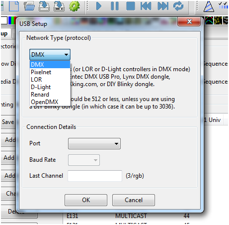
This option is to be used to define a DMX, Pixelnet, LOR dongle, DLight, Renard or OpenDMX setup. Each USB choice is described in the text found below the dropdown selection. As you select a different choice, the text assists you in identifying the best choice for your USB dongle.
Add E1.31
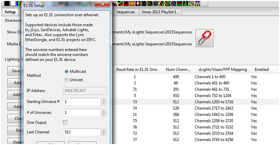
Clicking on the Add E1.31 button will display the following screen:
Select the Method (Multicast or Unicast) depending on which option you will use to drive your lighting networks. If unsure, leave as Multicast. If Unicast is selected, then the IP address of the controller that will support the universe(s) you are defining here must be entered. Enter the Starting Universe #, # of Universes and the Last channel for each universe. Leave the One Output unticked.
Note: If the ‘One Output’ is ticked, then visually the universes and number of channels will be grouped as follows:
The "Enable" value turns on/off that output when "Output to lights" is turned on. If it's not enabled, no output occurs. For example, if you have a controller not plugged in (testing a different controller) disabling that output would not attempt to send anything to that specific controller. Trying to send data to a controller that is not connected van in some cases cause delays and lags on the output.
Highlight the row and Double Click on it to toggle the value .
Tip: Most controllers only support 510 channels per DMX universe. The Falcon F16v2 controller supports up to 512 channels per universe. If configuring universes for a matrix that will be used on P10 panels, those universes should be defined as 512 channels per universe.
Tip: If you have a number of contiguous universes of a fixed number of channels you can enter the starting Universe #, a multiple of Universes and the Last Channel (number of channels), click OK and xLights/Nutcracker will create the universes for you. You can then modify the details after that. Alternatively, define each Universe by specifying the Universe # in the Starting
Universe # field, set the # of Universes to 1 and set the Last Channel to the number of channels in that section of the Universe. Press OK.
The following picture shows a configuration where:
● Universe 1 has 94 channels from Channel number 1 to 94
● Universe 2 then has 462 channels from Channel number 95 to 556
● Universe 71 has 291 channels from Channel number 557 to 847
● Universe 5 then has 453 channels from Channel number 848 to 1300 etc.
Note: If there are gaps in between, it is not required to specify the missing channels.
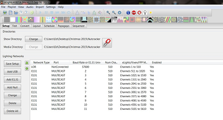
The following image describes a setup where a LOR network has been listed first. Even though only the first 32 channels of the LOR network are used, universe 1 has been defined as 510 channels in case more items are to be added to the LOR network without impacting the other channels above.
If universe 1 is set to 32 channels, then Universe 2 will start from 33 onwards that is also a valid configuration.
Add NULL
This type of setup is used as an example, where the sequence output will not be used by xLights/Nutcracker as a show player, but output data to be used for playback on a Raspberry Pi or BeagleBone Black controller.
There could be large matrices to be implemented via P10 or P5 panels running off a BeagleBone Black controller. A null output can reserve a huge number of channels, but not actually output anything if the Output to Lights function is on. A model can still be sequenced as normal and viewed on all the windows just as any other output.
Click on Add Null and specify the number of channels to be reserved. The corresponding number of channels will be created.
Note: If the Falcon Player on the Raspberry Pi or BeagleBone Black controller is to be used in ‘Bridge Mode’ (for testing via the sequencer prior to your show) then the universes and corresponding channels must be defined i.e. a definition of NULL will not output any lights.
Change, Delete or Delete All
To change or delete an individual row, highlight the row and select Change or Delete. Click on Delete All to delete the entire set up.
Saving your Setup
One you have done your additions or changes to the network setup, ensure you click on Save Setup to save your configuration.


